Fájl:Optical flat interference.svg
Ugrás a navigációhoz
Ugrás a kereséshez

Ennek a(z) SVG fájlnak ezen PNG formátumú előnézete: 715 × 599 képpont. További felbontások: 286 × 240 képpont | 573 × 480 képpont | 916 × 768 képpont | 1 221 × 1 024 képpont | 2 443 × 2 048 képpont | 1 417 × 1 188 képpont.
Eredeti fájl (SVG fájl, névlegesen 1 417 × 1 188 képpont, fájlméret: 48 KB)
Összefoglaló
| Leírás |
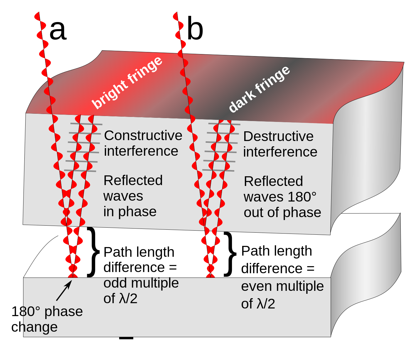
English: Diagram showing how interference fringes are created by an optical flat. The upper object is a section of a glass optical flat resting on another flat reflective surface. Light rays (red) from a monochromatic light source pass through the flat and reflect from both the bottom surface of the glass and the surface it is resting on. Since there is a tiny gap between the two surfaces, the ray reflecting off the bottom surface travels a greater distance than the top ray. It also experiences a 180° phase change at the reflection from the bottom plate (the reflection from the top plate causes no phase change). The parallel rays superpose. At locations (a) where the extra distance travelled by the 2nd ray (twice the width of the gap) is equal to an even multiple of a half-wavelength (λ/2) of the light the two reflected waves will be in phase and will add, reinforcing each other, resulting in a bright reflected ray. This is called constructive interference. At other locations (b) the path difference between the rays is equal to an odd multiple of λ/2, so the reflected waves are 180° out of phase. They subtract, canceling each other out, resulting in little or no reflected light. This is called destructive interference.
When the two surfaces are not parallel, as in the diagram, this results in a pattern of alternating bright and dark bands visible on the surface, called interference fringes. Two adjacent interference fringes represent a difference in height of the surface of one-half wavelength of the light used, so interference patterns can be used to measure the flatness of surfaces to millionths of an inch. In this diagram the width of the gap and the wavelength of the light waves is greatly exaggerated; light has wavelengths around 10-7 meter.Русский: Интерференция в тонком воздушном клине |
| Dátum | |
| Forrás | A feltöltő saját munkája |
| Szerző | Chetvorno |
| Más változatok |
|
| SVG kód |


Licenc
Én, e mű szerzője a művemet az alábbi licenc alatt teszem közzé:
| Ez a fájl a Creative Commons CC0 1.0 Univerzális Közkincs nyilatkozat alapján használható fel. | |
| Az a személy, aki ezen nyilatkozat hatálya alá helyezett egy művet, az egész világon lemondott minden, a szerzői jogi törvény szerinti műhöz fűződő jogáról, beleértve az összes kapcsolódó és szomszédos jogot is, a jogszabályokban megengedett mértékig. Ezzel a művet közkinccsé nyilvánította. Ezt a művet szabadon másolhatod, módosíthatod, terjesztheted vagy előadhatod, akár üzleti célból is, mindezt anélkül hogy engedélyt kellene kérned.
|
Fájltörténet
Kattints egy időpontra, hogy a fájl akkori állapotát láthasd.
| Dátum/idő | Bélyegkép | Felbontás | Feltöltő | Megjegyzés | |
|---|---|---|---|---|---|
| aktuális | 2022. január 16., 16:45 | | 1 417 × 1 188 (48 KB) | wikimediacommons>Aiden1123 | Reverted to version as of 03:54, 9 May 2017 (UTC) |
Fájlhasználat
Az alábbi lap használja ezt a fájlt: